
The Brain, the Heart, and the Muscle: How Your Thermostat, Indoor Unit, and Condenser Work Together
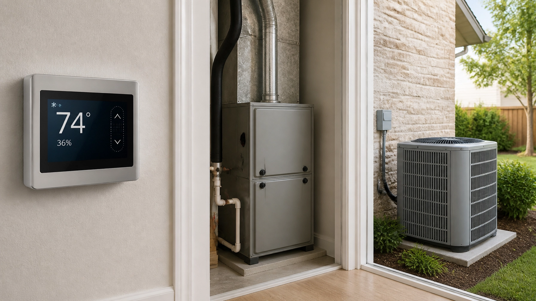
Your heating and cooling system is more than an air conditioner or furnace sitting in a closet. It is a team of components that must communicate with one another to keep your Austin-area home comfortable.
A helpful way to understand that team is to think of it as three parts:
- The thermostat is the brain. It measures indoor conditions and decides when the system should run.
- The indoor furnace or air handler is the heart. It manages airflow and coordinates much of the system’s operation.
- The outdoor condenser or heat pump is the muscle. It moves heat into or out of your home.
These components work together through low-voltage control wiring. The number and type of wires available can affect which equipment and thermostats are compatible with your home: especially in older Central Texas houses.

How the Three Main Components Work Together
A typical split-system air conditioner has an indoor unit and an outdoor condenser connected by refrigerant lines, electrical wiring, and control wiring.
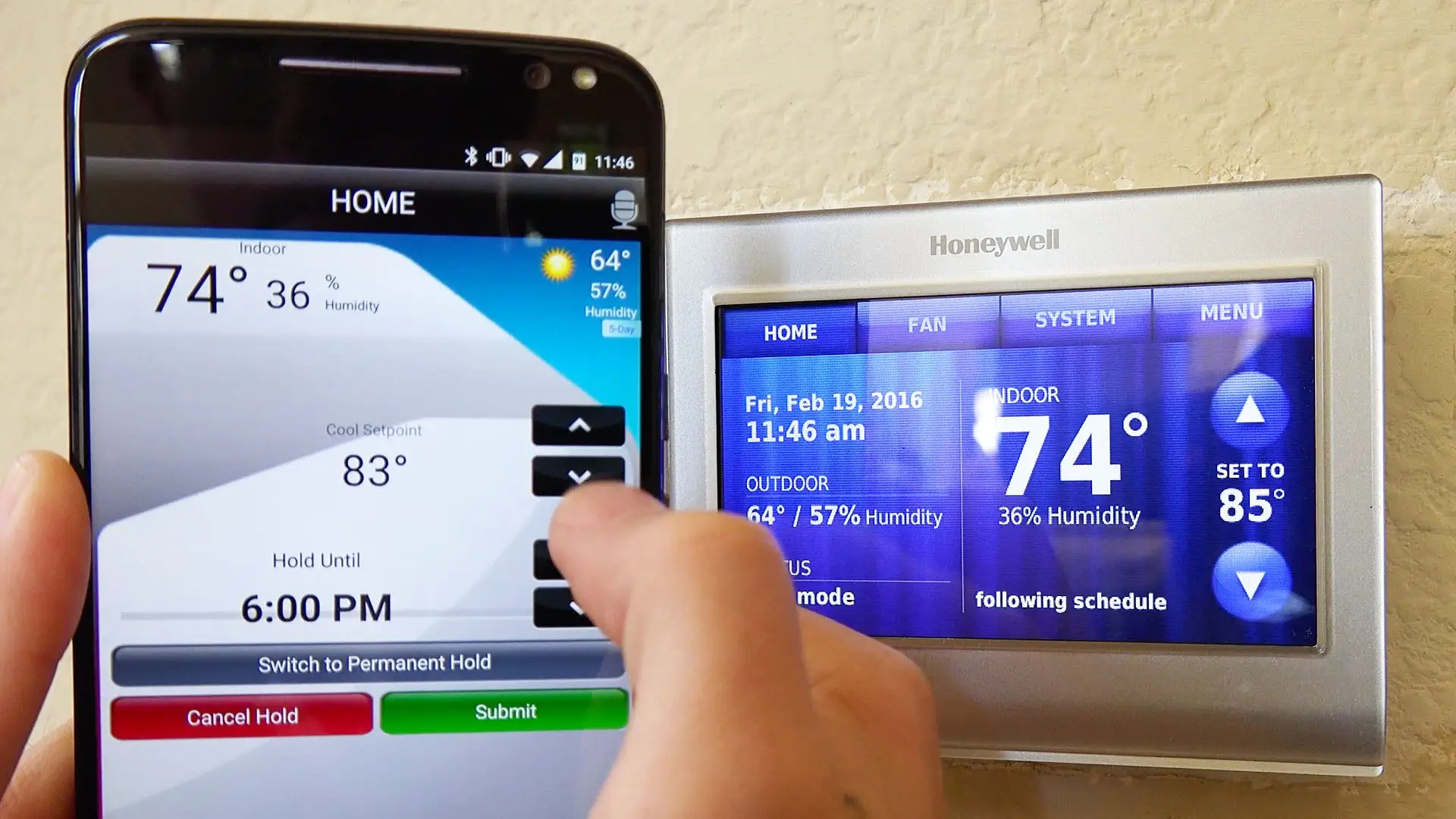
When your home gets too warm, the thermostat senses that the indoor temperature is above the set point. It sends a low-voltage signal to the indoor furnace or air handler. The indoor control board then responds by starting the indoor blower and signaling the outdoor condenser to operate.
The outdoor unit removes heat from the refrigerant and releases that heat outside. Meanwhile, the indoor coil absorbs heat from the air inside your home. The blower moves that cooled air through the ductwork and back into your living spaces.
The process reverses during heating when you have a heat pump. Instead of rejecting heat outdoors, the outdoor heat pump extracts available heat from outside air and brings it indoors. The thermostat and indoor equipment coordinate the heating mode, blower operation, and: when necessary: auxiliary or emergency heat.
In a conventional system with a gas furnace, the sequence is different. The thermostat calls for heat, the furnace starts its safety and ignition sequence, and the blower distributes warmed air after the furnace is ready.
What the Low-Voltage Wires Do
Most central HVAC thermostats use low-voltage control wiring, commonly around 24 volts. This is separate from the higher-voltage power that runs the compressor, blower motor, electric heat, and other major components.
The thermostat generally does not power those larger components directly. Instead, it sends control signals to the indoor unit’s circuit board. That board coordinates the sequence and passes the appropriate signals to the outdoor equipment.
Here are the most common thermostat terminals:
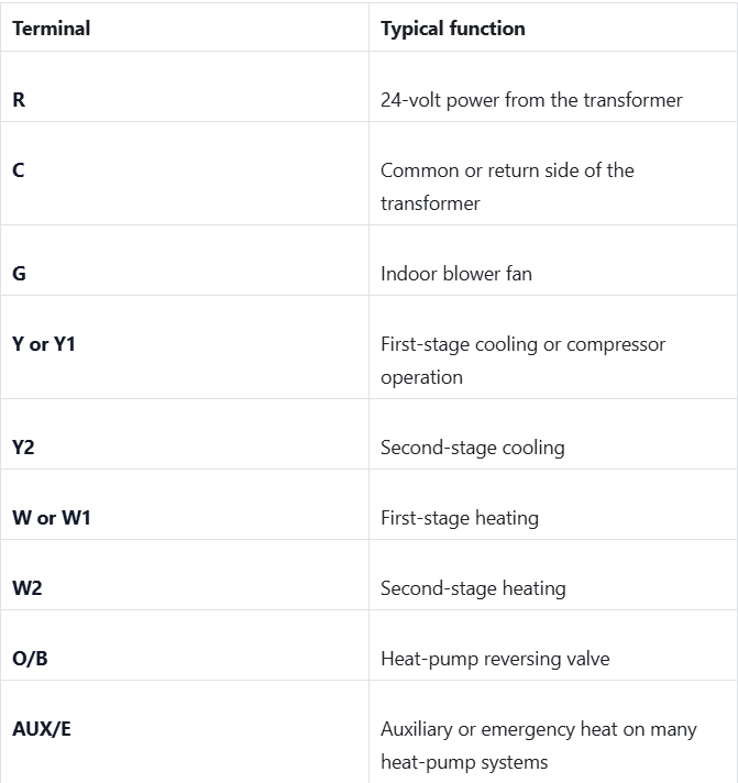
Wire colors are often traditional: red for R, blue or black for C, green for G, yellow for Y, and white for W: but colors are not guaranteed. The terminal label matters more than the color. This is also why taking a picture of the existing connections before replacing a thermostat is helpful.
Honeywell’s thermostat wiring guide provides a useful overview of common terminals and also emphasizes identifying wires by their terminal connections rather than relying on color.
A Basic Single-Stage System
A single-stage system has one operating level for heating and one level for cooling. The equipment is essentially either running at full capacity or turned off.
A conventional single-stage furnace and air conditioner commonly use:
- R for 24-volt power
- C for common
- W for heat
- Y for cooling
- G for the indoor fan
That is commonly a five-wire arrangement.
Some older thermostats use only four wires because they do not require a dedicated C-wire. For example, the thermostat may use R, W, Y, and G while receiving power through batteries or another method.
When the thermostat calls for cooling, it connects the R circuit to Y. The indoor control board recognizes the cooling call, starts the blower, and signals the outdoor condenser. When the thermostat calls for heat, it connects R to W, telling the furnace to begin its heating sequence.
This system is straightforward and can provide dependable comfort. It does not necessarily require a large number of control wires, which is one reason it is often easier to install in older homes.
Two-Stage Heating and Cooling
Two-stage equipment can operate at a lower capacity for ordinary comfort needs and use a higher capacity when the home needs more heating or cooling.
For example, a two-stage air conditioner may run in a lower stage during a mild afternoon. It can operate longer and more gently, which may help with temperature consistency and humidity control. If the indoor temperature rises significantly, the system can move to the second stage.
A two-stage furnace can do something similar. It may run at a lower heat output most of the time and bring on the second stage during colder conditions or when the home is not reaching the desired temperature quickly enough.
To control both stages directly, the thermostat and equipment usually need additional connections:
- Y1 for first-stage cooling
- Y2 for second-stage cooling
- W1 for first-stage heating
- W2 for second-stage heating
Depending on the equipment, a two-stage system may need seven or more conductors, including R, C, G, Y1, Y2, W1, and W2.
There is an important exception: some equipment can manage staging internally. In those systems, the thermostat may send a basic call and the furnace or air handler decides when to increase output. The number of wires alone does not tell the whole story, so equipment specifications and control-board connections should be checked before making assumptions.
Variable-Speed and High-Efficiency Equipment
“Variable-speed” often describes the indoor blower motor. Rather than operating at only one fan speed, the motor can adjust its speed to match the system’s needs.
The control board may choose the blower speed based on:
- Whether the system is heating or cooling
- Which stage is operating
- Temperature and airflow requirements
- Settings programmed into the indoor equipment
A variable-speed blower does not always require a separate thermostat wire for every possible fan speed. In many conventional systems, the thermostat still sends familiar signals such as W, Y, and G, while the indoor unit determines the appropriate blower speed.
However, high-efficiency equipment may include more advanced controls. The exact wiring requirements depend on the manufacturer, equipment combination, and thermostat.

Communicating Systems Use a Different Language
Fully communicating systems are the most advanced part of this range. Instead of using separate on-and-off signals for every function, the thermostat, indoor unit, and outdoor unit exchange digital information.
A communicating system may continuously share information such as:
- Indoor and outdoor temperatures
- Humidity
- Operating capacity
- Airflow requirements
- Equipment status and fault information
- Maintenance reminders
- The amount of heating or cooling the home needs
This allows the system to make smaller, more precise adjustments. A variable-capacity outdoor unit, variable-speed indoor blower, and communicating thermostat can work together to deliver more consistent comfort than a basic on/off system.
There is an important wiring distinction here. Conventional staged equipment generally needs more individual control conductors as more stages are added. Communicating equipment often uses a dedicated data-and-power connection rather than separate R, W, Y, and G commands for every function. It may use fewer wires overall, but those wires and terminals are not interchangeable with standard thermostat wiring.
Communicating systems usually require the manufacturer’s specific thermostat or an approved control. A generic smart thermostat may not be able to access the system’s capacity adjustments, diagnostics, humidity management, or other features. In some cases, installing the wrong thermostat can reduce the system to limited operation: or make it incompatible altogether.
If you see terminals labeled something like A, B, C, 1, 2, 3, or data, do not assume they function like conventional R-W-Y-G terminals. The manufacturer’s wiring instructions are essential.
Why Older Austin Homes Can Present a Wiring Challenge
Many older homes were built with only the wiring needed for the equipment installed at the time. You may find:
- A two-wire setup for basic heat-only control
- A four-wire setup for a conventional heating and cooling system without a dedicated C-wire
- Unused wires tucked behind the thermostat
- A cable that does not contain enough conductors for two-stage operation
- Wiring that is damaged, disconnected, or difficult to trace
This matters when installing a Wi-Fi thermostat or upgrading to two-stage, variable-capacity, or communicating equipment.
A smart thermostat commonly needs a C-wire for continuous power. Without it, the thermostat may not operate reliably, may drain batteries quickly, or may not be compatible. Similarly, a home without spare conductors may not be able to use separate W2 or Y2 calls from a conventional multi-stage thermostat.
What Are Your Options?
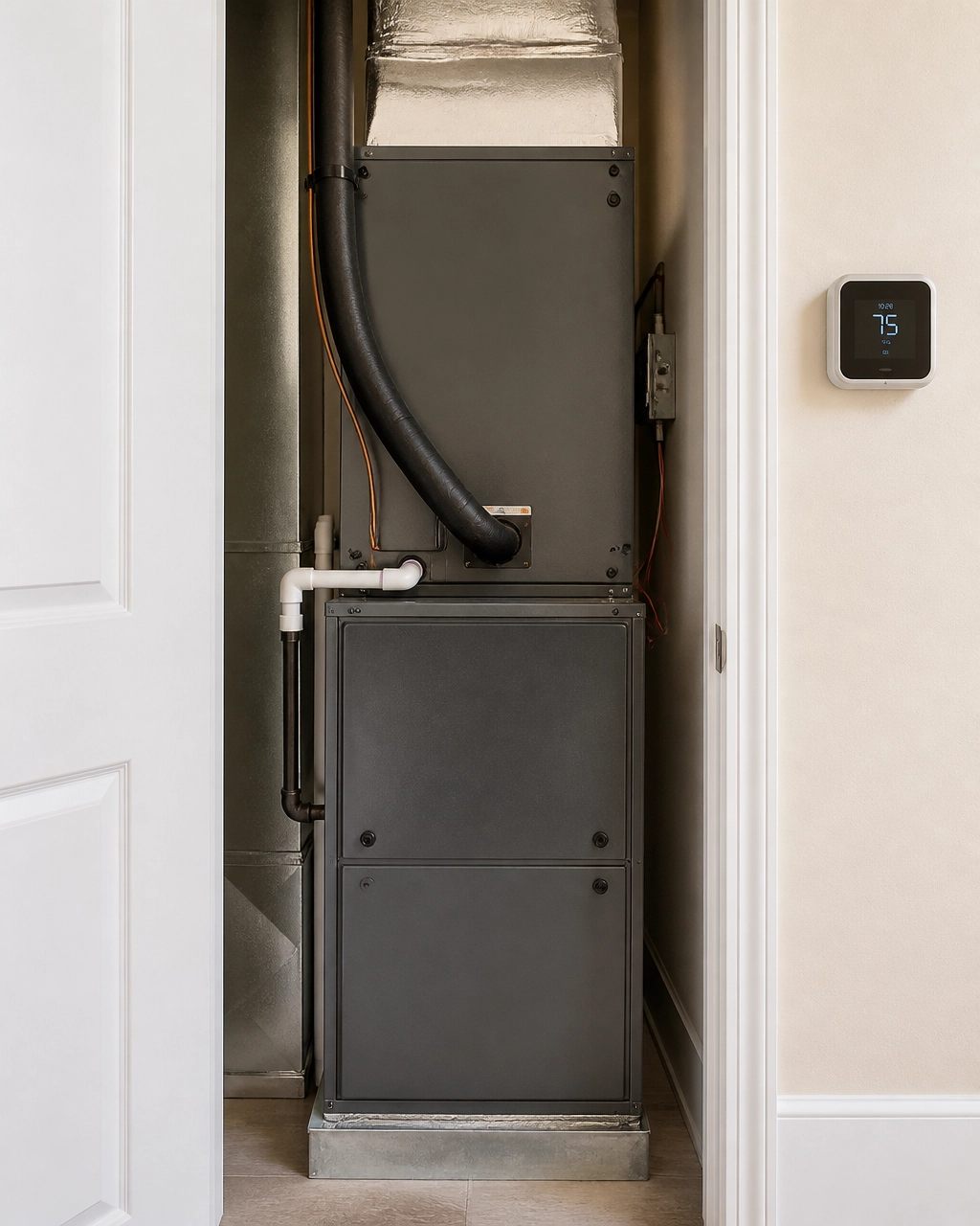
A wiring limitation does not automatically mean you cannot upgrade. The right solution depends on the existing cable, equipment, thermostat, and access inside the walls.
Possible options include:
- Use an existing unused conductor.
Sometimes an extra wire is already present in the thermostat cable but was never connected. A technician can verify where it terminates and whether it can be used for C or another control function. - Install an add-a-wire adapter.
Certain adapters can create a C-wire connection for compatible conventional systems by combining signals through existing conductors. These devices do not work for every system and are generally not a substitute for the dedicated wiring required by many communicating systems. - Pull new thermostat cable.
Running new control wiring is often the cleanest long-term solution when access allows. It provides the conductors needed for the selected thermostat and equipment and avoids forcing a system to operate with limited features. - Choose compatible equipment.
Sometimes the most practical choice is equipment that matches the home’s existing wiring. That may mean selecting a system with internal staging or a compatible thermostat rather than choosing equipment that requires extensive rewiring.
The best option is not always the most expensive one. It depends on your goals, budget, the condition of the existing system, and how long you plan to stay in the home.
The Bottom Line
Your thermostat, indoor unit, and outdoor condenser must communicate as a team. Basic single-stage systems use a few simple low-voltage signals. Two-stage systems generally need additional conductors for their extra heating and cooling stages. Variable-speed equipment may manage many adjustments internally, while fully communicating systems use a proprietary digital language and matched controls.
Before replacing a thermostat or selecting new HVAC equipment, have the existing wiring and control system evaluated. At Accu-Temp Air Conditioning & Heating, we work with systems ranging from older conventional equipment to modern communicating systems. Our goal is to provide a factual diagnosis, explain your options clearly, and help you make an informed decision: without unnecessary repairs or upselling.
If you are planning an upgrade, you can also learn more about new system installations or smart thermostat setup. A properly matched thermostat and HVAC system can make a meaningful difference in comfort, efficiency, and reliability.